Ultrasonic Smart Gas Meter
Advanced digital ultrasonic natural gas meters ensure precise and dependable measurement of natural gas consumption. Unlike conventional mechanical meters, they utilize ultrasonic waves to gauge gas flow, enhancing measurement accuracy and eliminating meter reading errors. These meters systematically collect, process, and transmit consumption data digitally to central systems in real time. With their intelligent capabilities, they facilitate remote monitoring and management, allowing both consumers and energy management systems to efficiently track natural gas usage. By leveraging digital and wireless communication technologies, smart ultrasonic meters enhance billing transparency and optimize energy efficiency. Moreover, they assist in cost savings by analyzing gas consumption patterns and significantly enhancing the user experience.
Read moreNatural Gas Switch
Natural gas safety switches, specifically engineered to enhance the security of natural gas systems, serve as essential protective devices that automatically interrupt gas flow when system pressure exceeds predetermined thresholds. In the event that the pressure level surpasses or falls below the designated limits, the switch promptly halts the natural gas supply, thereby mitigating potential hazards. Functioning similarly to electrical circuit breakers, this mechanism is designed to prevent gas leaks, equipment malfunctions, and other associated risks.
Read moreSingle Stage Gas Pressure Regulators
Single-stage gas regulators are straightforward and effective devices engineered to regulate gas flow by reducing the inlet pressure to a predetermined level. Due to their compact design, they facilitate ease of operation and require minimal maintenance. Commonly utilized in industrial, commercial, and residential applications, these regulators enhance system stability by minimizing pressure variations and ensuring a secure and consistent gas flow. Providing benefits in terms of energy efficiency and operational safety, single-stage gas regulators are manufactured in compliance with applicable legal and regulatory standards, guaranteeing long-term reliability and safe usage.
Read moreStation Solutions
The term "RMS" refers to "Regulating and Metering Station," which is legally and technically recognised in Turkish as "Gaz Basıncı Düzenleme ve Ölçüm İstasyonu." Within the scope of our product portfolio, RMS stations are classified into distinct categories, including RMS-A (Compact, Containerised, and Twin Unit types), RMS-B, RMS-C, and skid-mounted systems. These Pressure Reduction and Measurement Stations (RMS) serve the operational purpose of reducing medium- to high-pressure natural gas from the transmission line to a regulated pressure level and facilitating accurate measurement of gas consumption. Natural gas enters the RMS facility through a designated inlet valve, subsequently passes through filtration units designed to eliminate particulate matter, and then undergoes pressure regulation via certified pressure-reducing devices. This series of operations ensures the delivery of natural gas at a stable and predefined outlet pressure level. Following pressure regulation, the gas is directed to the metering unit, which is configured either as a single-line or as a multi-line system depending on the operational design. To maintain continuity of service during scheduled maintenance or unforeseen malfunctions, gas pressure regulation and measurement units may be constructed with a dual-line configuration. This dual-line system provides redundancy, thereby ensuring uninterrupted gas supply and compliance with applicable safety and reliability standards.TECHNICAL SPECIFICATIONSThe technical specifications of the products are set forth below. These values may differ based on specific station parameters, including but not limited to outlet flow rate, outlet pressure, and inlet pressure range.Definitive technical data is provided on the product's identification label.
Read more Steel Filter Series
Cartridge-type steel filters are designed to safeguard downstream components such as regulators, valves, and meters from potential deterioration or damage by eliminating contaminants and foreign particles from the gas stream. Standard filter units are capable of removing particles with a size of 5 microns and above. Within the natural gas sector, a typical acceptable pressure drop across the filter cartridge is 100 mbar; however, this value is subject to variation based on operational requirements and can be specified within a range of 50 to 500 mbar at the time of ordering. These cartridge filters channel the incoming gas from the inlet port towards the lateral surfaces of the filter housing. As the gas traverses through the filtration media, solid particles at the micron scale are retained on the external surface, while entrained liquid droplets adhere to the outer walls. The purified gas then passes through the cartridge interior and exits via the outlet port. Unless expressly stated otherwise, each filter is equipped with a differential pressure gauge to monitor clogging levels, suitable for integration with SCADA systems. The gauge offers a measurement signal range of 0-1000 mbar, includes a dry contact output, and is pre-set to activate an alarm at 250 mbar unless alternate settings are requested. Solid and liquid accumulations must be discharged manually through the designated drain port located at the filter's base at defined intervals, and the cartridge should be cleaned or replaced concurrently. Cartridge replacement is straightforward and efficient. All filter units are produced in compliance with API 1104 standards. The overall filtration performance is influenced by various factors, including the structural design of the cartridge, frequency of maintenance, degree of gas contamination, system pressure, and gas flow velocity. Optional features include the integration of a Quick Opening Closure (QOC) for expedited access. Upon request, galvanized or stainless steel support plates can be mounted on the interior and exterior surfaces, as well as the top and bottom sections of the filters. Where radiographic inspection is impracticable, alternative non-destructive testing techniques may be employed to assess weld integrity.• Application Areas: Applicable to gas transmission and distribution pipelines, pressure regulation and metering stations, as well as commercial and industrial gas systems, among other similar installations.• Permissible Fluids: Natural gas, atmospheric air, LPG, propane, and other non-corrosive gaseous substances.• Capacity Specification: Determined in accordance with the requirements of each specific project.• Nominal Bore Sizes: DN25 through DN300.• Pressure Ratings: Conforming to Class 150, Class 300, Class 600, PN6, PN16, PN25, and PN40 standards.• Cartridge Classifications: Ranging from G0.5 to G3.• Connection Configuration: Available in both in-line (straight) and angular formats.• Filtration Efficiency: Equal to or exceeding 98%.• Drainage Outlet Size: DN15 to DN25.• Flange Connection Type: Provided with either gasket-sealed raised face flanges or welding neck flanges.• Permissible Operating Temperature: From -20 °C to +60 °C.• Dimensional Specifications: Tailored in accordance with project-specific parameters.• Certification and Standards Compliance: Designed and manufactured in compliance with ASME Section VIII Division 1.• Testing Procedures: Subject to hydrostatic testing at 1.5 times the design pressure (PSx1.5) and pneumatic testing at 1.1 times the design pressure (PSx1.1).
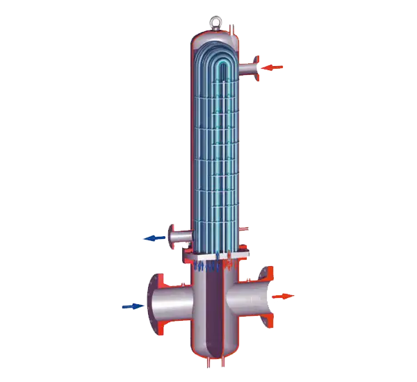
Read moreHeat Exchanger RMS-A Type Natural Gas Stations
Gas Heating Process and Use of Pipe-Type Heat Exchangers in RMS-A Type FacilitiesRMS-A type natural gas facilities constitute critical infrastructure in which high-pressure gas is reduced in a controlled environment to facilitate safe delivery to end users. Prior to the execution of the pressure reduction process in these facilities, it is a mandatory operational requirement to subject the gas to a heating procedure. The fundamental rationale for this requirement is the significant temperature drop that occurs during pressure reduction, which may result in frost formation and pose a risk of mechanical damage to station components.Legal Basis for Gas HeatingAs the pressure differential between the gas inlet and outlet points increases, the temperature of the gas correspondingly declines, a thermodynamic phenomenon known as the Joule-Thomson effect. This temperature reduction may cause the water vapour present in the gas stream to condense and crystallise into ice. The formation of such ice particles can adversely affect or render inoperative critical components such as regulators, valves, metering devices, and safety mechanisms, thereby potentially compromising the integrity of the entire system.Implementation of Pipe-Type Heat ExchangersTo mitigate this risk, pipe-type heat exchangers are integrated into RMS-A type facilities. These units serve to elevate the temperature of the gas prior to pressure regulation, thereby compensating for thermal losses and preserving system stability. The design and engineering calculations of these heat exchangers are specifically based on the principles of the Joule-Thomson effect to ensure their efficacy under operational conditions.Manufacturing Standards and Regulatory ComplianceAll heat exchanger units are manufactured in strict adherence to globally recognised engineering and safety standards. Specifically, the design, fabrication, and testing processes conform to the provisions of ASME Section VIII, Division 1. Compliance with these standards guarantees structural integrity, operational reliability, and long-term performance in accordance with legal and technical obligations.
Read moreRegulator Spare Parts
Medium and high-pressure regulators, commonly utilised in natural gas and industrial gas pipeline systems, are essential for maintaining the safety and operational efficiency of such infrastructure. However, due to prolonged exposure to gas flow and pipeline contaminants, internal regulator components may be subject to wear, obstruction, or physical deformation, thereby necessitating routine servicing and part replacement.Legal Justification for Regulator MaintenanceGas transmission lines—particularly those operating under high load conditions—frequently transport particulate matter, moisture, and other foreign substances. Over time, such contaminants may cause:Mechanical fatigue and degradation of diaphragm materials,Compromise of gasket sealing capability,Clogging or impairment of internal regulator assemblies.These conditions may result in pressure instability, reduced system performance, and potential safety hazards. Accordingly, regular inspection and maintenance of regulators is a legal and technical necessity for ensuring system integrity and compliance with applicable safety standards.Spare Part Procurement for Eska RegulatorsDespite the robust and enduring design of Eska brand regulators used in medium and high-pressure applications, periodic replacement of internal parts may become required. In this context, our company ensures full support for all Eska regulator models, including:Project-specific spare parts lists prepared in accordance with technical requirements,Series-specific boxed spare part kits,Comprehensive assistance and guidance throughout the process.Upon receipt of a formal request, the necessary spare parts are dispatched without delay, enabling maintenance operations to be conducted efficiently, safely, and in line with regulatory and manufacturer specifications.The term "RMS" refers to "Regulating and Metering Station," which is legally and technically recognised in Turkish as "Gaz Basıncı Düzenleme ve Ölçüm İstasyonu." Within the scope of our product portfolio, RMS stations are classified into distinct categories, including RMS-A (Compact, Containerised, and Twin Unit types), RMS-B, RMS-C, and skid-mounted systems. These Pressure Reduction and Measurement Stations (RMS) serve the operational purpose of reducing medium- to high-pressure natural gas from the transmission line to a regulated pressure level and facilitating accurate measurement of gas consumption. Natural gas enters the RMS facility through a designated inlet valve, subsequently passes through filtration units designed to eliminate particulate matter, and then undergoes pressure regulation via certified pressure-reducing devices. This series of operations ensures the delivery of natural gas at a stable and predefined outlet pressure level. Following pressure regulation, the gas is directed to the metering unit, which is configured either as a single-line or as a multi-line system depending on the operational design. To maintain continuity of service during scheduled maintenance or unforeseen malfunctions, gas pressure regulation and measurement units may be constructed with a dual-line configuration. This dual-line system provides redundancy, thereby ensuring uninterrupted gas supply and compliance with applicable safety and reliability standards.TECHNICAL SPECIFICATIONSThe technical specifications of the products are set forth below. These values may differ based on specific station parameters, including but not limited to outlet flow rate, outlet pressure, and inlet pressure range.Definitive technical data is provided on the product's identification label.• Application Area: Applicable in gas transmission and distribution networks, as well as in commercial and industrial gas installations• Compatible Fluids: Natural gas, air, LPG, and other non-corrosive gases• Inlet Pressure Range: 1 - 25 bar (Subject to project requirements) (Up to 75 bar for RMS-A configurations)• Outlet Pressure Range: 0.3 - 4 bar (Subject to project requirements) (Up to 20 bar for RMS-A configurations)• Capacity Range: 50 - 20,000 m³/h (Subject to project requirements) (Up to 1,000,000 m³/h for RMS-A configurations)• Nominal Diameters: DN25-DN300 (Determined by project specifications)• Flange Standards: PN or ANSI compliant• Number of Lines: Single or dual line setup (Project-dependent)• Operational Temperature Limits: -20°C to +60°C• Accuracy Class – Outlet Pressure Deviation: AC5/AC10• Integrated Filter: Included• Dimensions: To be determined in accordance with project design• Standards and Certification: Complies with Botas, TS EN 12186, ASME, ISO 9001, ISO 14001, ISO 45001
Read more